
Free Online AES256 Encryption Tool
Wrelks' free online AES256 encryption tool, It's fast and easy!

One of my larger side projects has been creating a battery pack using custom designed fast charging technology, and utilizing kinetic energy. Battery packs are fun things that can be built at home with relative ease and without burning a hole in your wallet. If you have decent circuit/PCB design and manufacturing knowledge you can easily design your own battery pack at home.
For those maybe a little confused on the term ‘fast charging’, it pretty much means charging that utilizes a much higher wattage then normal USB charging solutions. For example a battery pack that can charge a phone at 15 watts would be considered a fast charging capable battery pack. Whereas the normal charging rate is usually around 5 watts.
To be clear this board is NOT the entire battery pack logic. It’s actually a separate print of the logic which takes in a high amperage 5V USB input and lowers it down to 4.2V at around the same amperage of the initial input. So this would be the initial set of logic that the USB power would go through then after it’s been shifted down, out to the LiPo it goes.
analog.com has a wonderful in-depth tutorial discussing how voltage step down circuitry works. Check it out!
The battery pack that I have been designing utilizes a 3.7V LiPo battery. LiPo batteries are the same batteries that you’ll find in many of modern day handheld electronics, laptops, phones, tablets, and many more. But wait, 4.2V? Isn’t the battery rated at 3.7V? Well the 3.7V simply stands for the voltage input that the LiPo battery is capable of, and the voltage the battery will remain at for a large majority of it’s lifespan. The battery it’s self can be charged with a voltage range of 3.7V - 4.2V.
One of the most difficult parts of designing circuitry is picking out the ICs (Integrated Chips) that you want to use. Many things have to come into consideration. Package of the IC, can it be manufactured onto a PCB, what temperature range can it operate at, what the maximum/minimum amperage/voltage, does it have any charging safeguards, is it configured out of the box or does it have to configured to a certain amperage rating with external capacitors and resistors. These are all of the things that come to mind when picking out a chip to fit your design. Thankfully charging solutions are a very popular market and thus there are many different charging ICs to choose from. So where do I find these ICs to pick from? I personally use either Mouser or DigiKey to search for ICs to use in my builds. When you find the IC that sounds appealing based off it’s highlighted specs you can then read the datasheet of said IC to learn more about the chip to see if will fit your application. I personally looked for a IC that was rated for charging LiPo batteries, could output anywhere from 3.7V - 4.2V, and could handle high amperage. The chip that I settled on could do just that what I’ve mentioned but with a catch. A single chip couldn’t handle extremely high amperage, they would need to be a put in a series. This is why you see 4 of the same looking IC on the board.
TIP: 99% of IC datasheets will come with schematic examples to give you an idea for how to use the chip in practice.
The main goal when looking for a manufacturer is to find one that’s cheap, fast, and is good for the quantity of product you are wanting. What I mean by the last statement is that there are some manufacturers that are better for low quantity shipments and others for high quantity. I personally was looking into ordering 10 boards so I went with a pretty well known PCB manufacturer known for low quantity orders, JLPCB. In about 5 days my boards were here! The other big aspect I look out for when looking into PCB manufacturers is seeing whether they support automatic placing of the ICs themselves or if it’s exclusively PCB stencil manufacturing. Many manufacturers print the actual board stencil but without the chips soldered on. Thankfully JLPCB supports pre-soldered ICs for a little extra cost.
Now that everything has arrived it was time to put it all to test. For the test I will be inputting a 5V 2Amp input and expecting a 4.2v ~2Amp output. Before I get into this test I believe a little tour on the surface of the board is in order for some context.
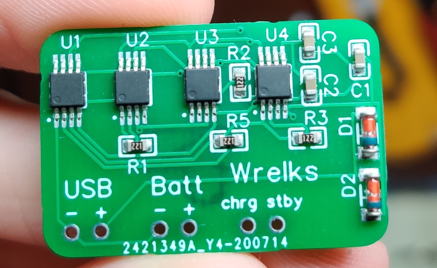 Final Product
On the left side you’ll find the USB input, and their corresponding polarization can be found by the plus and minus above the copper hole.
In the middle is the battery output terminal, here is where the stepped down 4.2 volts result will come from.
On the right side you’ll find the ‘status’ terminal. The IC that I chose has two different signifier flags built into it. One being chrg which when LOW means that the battery is currently charging. The other status flag is the stby, this flag when LOW means that the battery is completely charged.
So after some thorough testing, it appears that the circuit Works! It was successfully able to charge up a 3.7V 5,000mah LiPo battery! I hope this little write up was either useful / fun to read and I hope to release more of these in the coming future! See you then.
Wrelks' free online AES256 encryption tool, It's fast and easy!
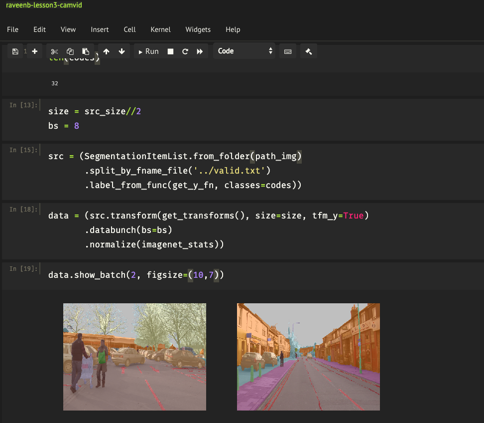
How to install Jupyter Notebook, the dos and don'ts!
When I got my hands on a Ryzen 5900x CPU shortly after launch, I experienced some thermal issues. Here's how I fixed it.